3D printer setup: Kinematics
Introduction
The temperature tower printed as first part can be used to determine the periodic errors as well. In case of a filament that differs a lot between temperatures, you may need to change the script to print the object at constant temperature.
Periodic errors in A/B
The axes may move smooth, but most rotating parts like pulleys produce periodic errors, which includes bearing balls in idlers and linear bearings. Additionally the gear teeth of transmissions and belts produce periodic errors as well. The more parts with different periods get mixed, the worse it gets. I learned that a CoreXY with its many idlers is not the best design when it comes to periodic errors.
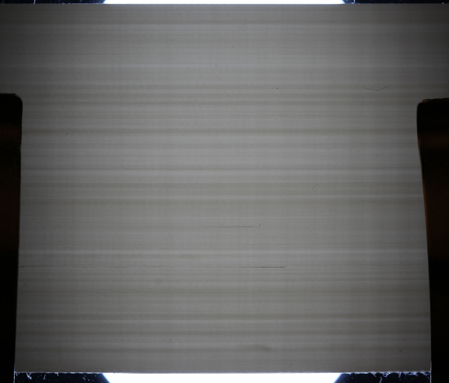
Extreme low angle light from the side turns the smooth surface of a heat tower diagonal above into a landscape of mountains and valleys. The image is not unsharp, but the structures are quite weak, even with extreme light. The visual inspection shows a pattern that is too stable for being caused by the extruder. Diagonal side for moving A motor:
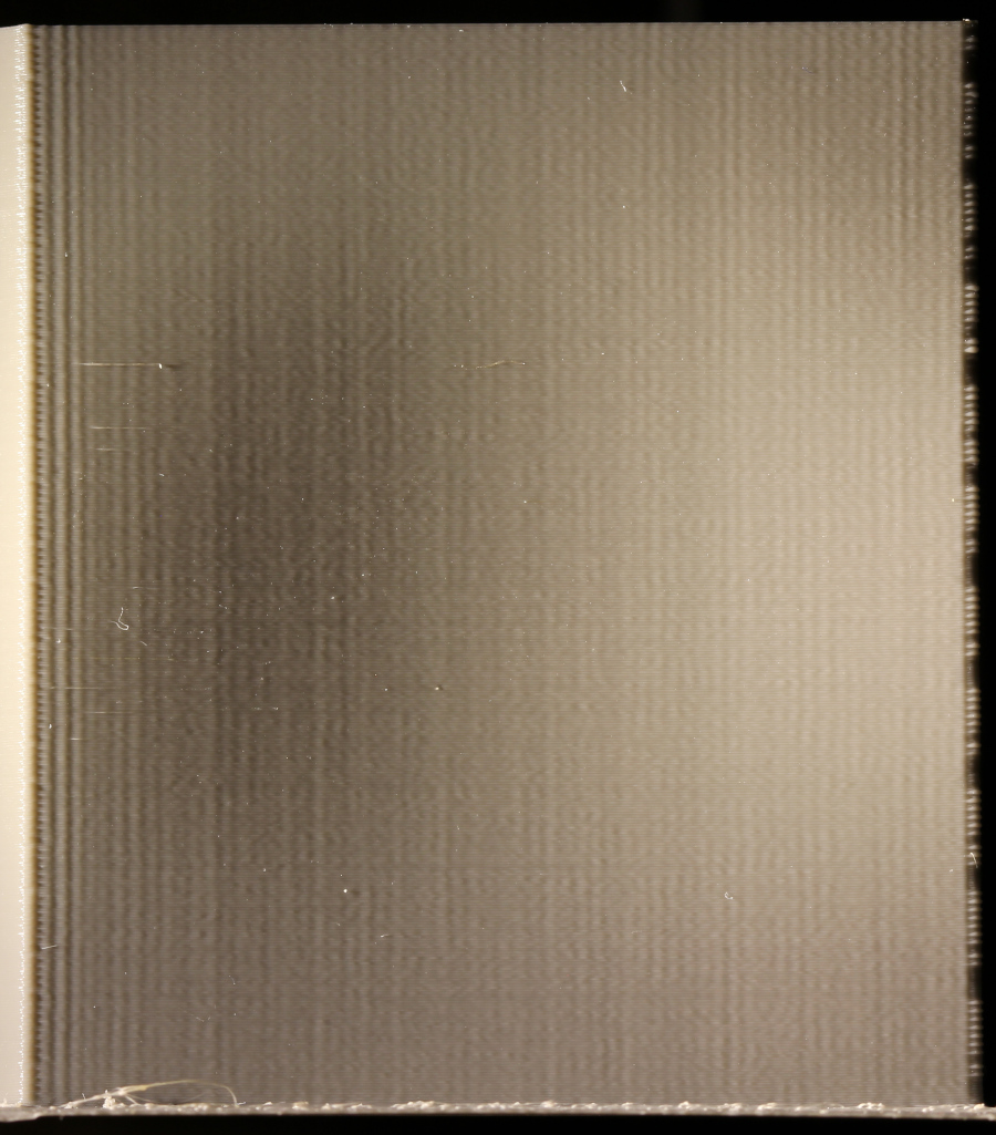
I acquired two images and used ImageJ to take 3 scan lines from each image, performed a FFT of the detrended and zero-based data and converted the spectrum to wavelengths in mm.
The FFT shows a peak at 0.6 mm. That is higher than any periodic error. At 30 mm/s print speed it is a time frequency of 50 Hz, which is suspiciously near the natural frequency of the belt. The other peaks are caused by the significant gradient. Anything else would be a surprise, given that only one motor works at a time:

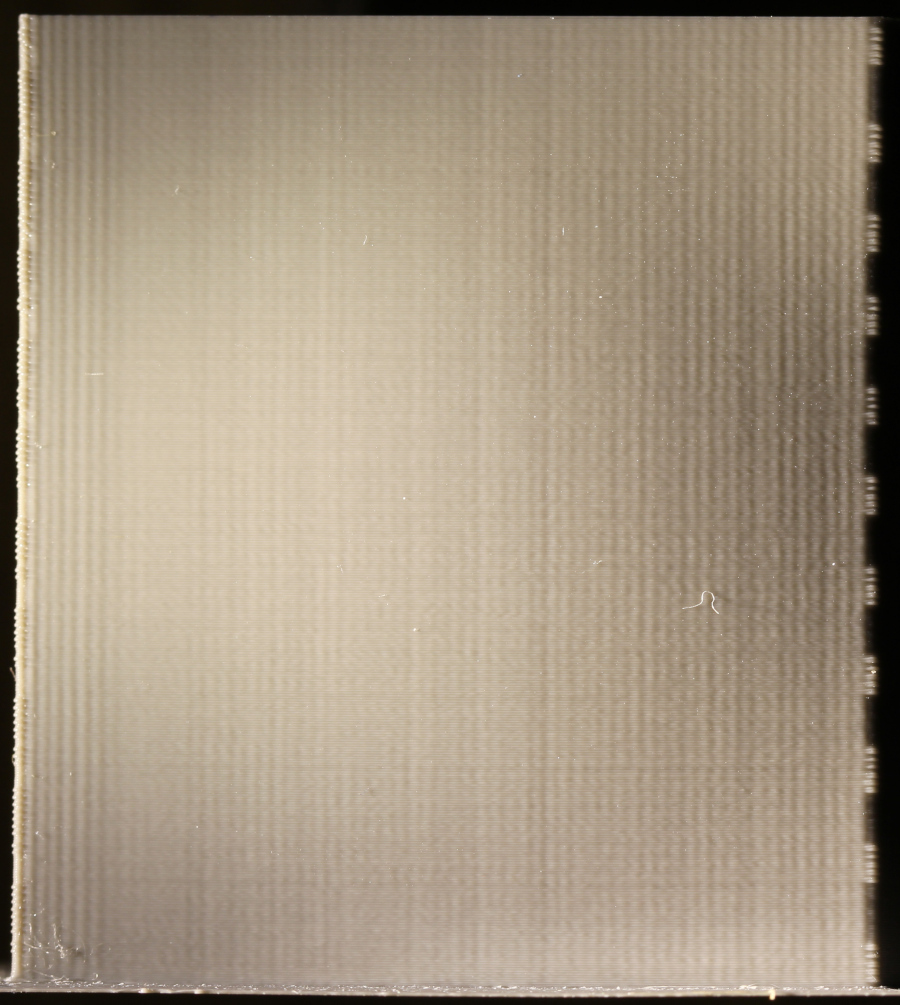
The diagonal side for moving B motor looks similar:
Periodic errors in X/Y
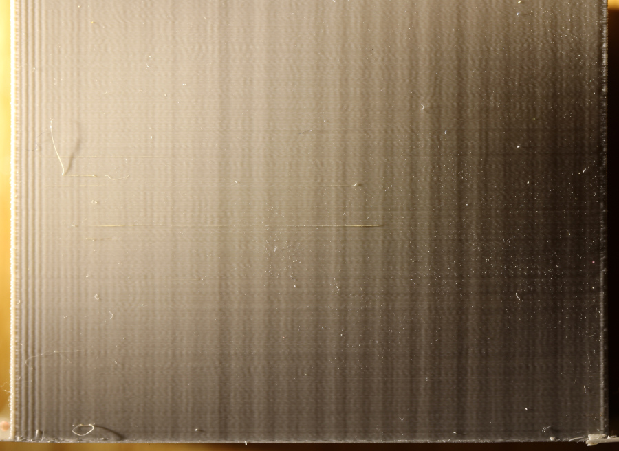
If two motors work together, periodic errors will interfere and get visible. A CoreXY moves both motors in X and Y, whereas a cartesian drive moves both in diagonals. The visual inspection shows a much different surface for X:
The FFT acknowledges that:

The 0.6 mm peak is present as well, although each motor moves slower in X/Y than for a diagonal, so the wavelength correlates with the tool speed, not the motor speed. The 2 mm peak matches the GT2 belt tooth period and the stable position agrees with that. The other frequencies are not as well defined, perhaps caused by pulley and idler tooth precision.
The gradient forbids analysis of larger wavelengths than shown above. Again a small program to generate a a set of parallel lines in Y direction helps:
![]() Script to generate lines pattern
Script to generate lines pattern
![]() Script to move the
print head in circles
Script to move the
print head in circles
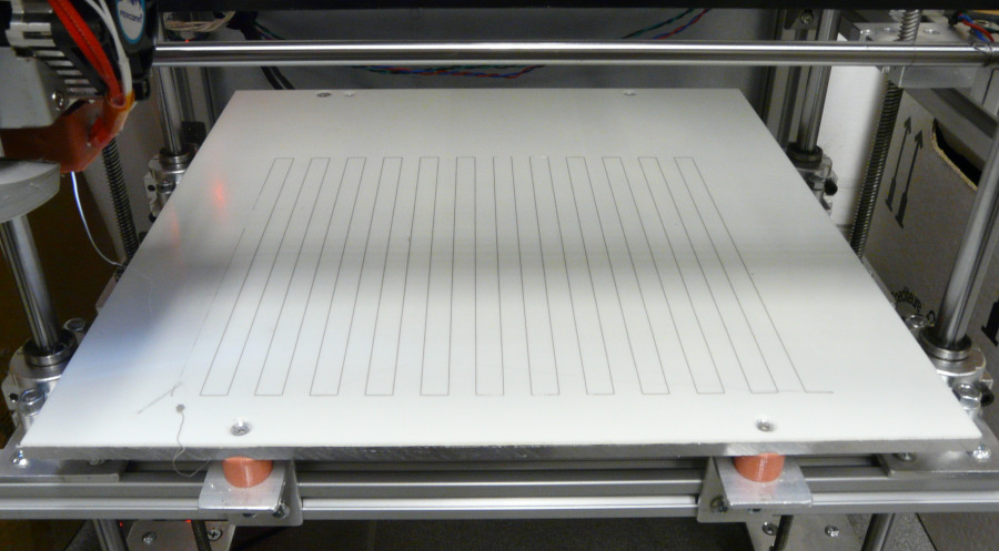
This test also verifies the calculation on steps/mm were correct. Many people print parts for that calculation, but parts may shrink, warp or show other distortions. Simple tracks printed on the bed don't and allow to verify both short and long distances.
Periodic errors in Z
Periodic errors in Z cannot be determined like that, because any imperfection in XY positioning that slightly shifts a layer will look like a Z error with low angle light. True Z errors change the layer height, which effects the layer width, and the latter can be determined by light absorption. I cut out 30 mm of the temperature tower and put it on a transmission-light unit intended for a cheap microscope.
The scan lines were taken from the middle, because at the borders differences in reflection starts to influence the image.

The peak at 0.1 mm is the layer height, because layer edges are not rectangular, but curved, so the walls are slightly thinner where layers bond. This peak as well as most short wavelengths next to form kind of a noise floor which I attribute to resistance in the axis bearings. The spindles have considerable mechanical play and the build bed is only held down by its considerable weight. The giant peak at 7 and 8 mm dominates and can be recognized visually when viewing the image from a distance. I suspect the cheap trapezoidal spindles to cause that, because the periodic errors from the pulleys are all very different. The maximum brightness deviations are +- 20%, which means at 0.1 mm layer height, around +- 2/100 mm. The specification of common trapezoidal spindles allows way more than that! Again the gradient forbids analysis of larger wavelengths, but the result is reasonable up to 10 mm wave length.
Most likely this is at the upper end of trapezoidal spindle accuracy and more required a good ball screw. Contrary to common belief, this also means that the flow cannot be controlled precisely for thin layers.
Periodic errors in extruder gear
If the extruder gear is eccentric, damaged or dirty, the filament transport will contain a periodic error that causes layers to be more or less wide, similar to periodic errors in Z, but typically the period is prime to the number of layers and the result looks like a random error. This can be changed by using the right track length per layer:
$${ 1.75 \text"mm" / 2 }^2 · π = 2.4 \text"mm"^2$$ $$0.2 \text"mm layer height" · 0.3 \text"mm layer width" = 0.06 \text"mm"^2$$ $${ 2.4 \text"mm"^2 } / { 0.06 \text"mm"^2 } = 40 { \text"mm layer length" } / { \text"mm filament" } $$ $$7.3 \text"mm gear diameter" · π = 22.92 \text"mm filament" = 916.8 \text"mm layer length" $$
The layer length must be distributed in Z in a way that is very different to the existing periodic error of the kinematics, but still well visible for analysis. My trapezoidal spindles show around 7–8 mm period. Distributing the extruder gear error to 3 mm period should be fine, which results in 15 layers with the total length 916.8 mm. A small tower of 5 mm depth and 25.56 mm width does fine.
![]() Script to generate extruder tower
Script to generate extruder tower
The analysis is the same as for the periodic error in Z, but to my surprise, I still only got peaks for the layer height and the spindle error. Wondering why the overall frequency spectrum looked better, I realized that the only other change was to move from Marlin's TMC hybrid mode to spreadCycle, because the hybrid mode showed to be buggy. Obviously the increased torque of spreadCycle leads to a lower positioning error in Z for my printer.
Natural frequency
Unlike e.g. a CNC mill, 3d printers are not extremely stiff devices and that shows in their natural frequency. I mounted an acceleration sensor to the frame, put the print head at the center and moved with 30 mm/s by 15 mm at 30 mm/s jerk speed, which creates a 0.5 s movement with instant stop. Since the speed change happens instantly, it is a Dirac pulse and excites the natural frequency of the printer.
The movement in X shows vibration during the movement that is likely caused by the belt and quickly stops when the movement stops. The lower mass in X does not excite the frame at this speed.

The FFT shows 46 Hz as dominant frequency, which is near the natural belt frequency. I don't know what excites the belt so much.

The Y axis has higher mass and that shows by an acceleration and deceleration peak that suffices to excite the frame:

The FFT shows X is still heavily ringing, which is no surprise, because a CoreXY always moves both motors and belts for moving in X and Y. The dominating peaks in Y are at 20 Hz and 46 Hz. The higher mass and the soft X-Axis with its two shafts is not ideal.

Summary: The ringing period is around 1/46 Hz = 20 ms, so being conservative my deceleration time should be at least 30 ms to let the acceleration not excite the natural frequency badly. To calculate the right acceleration I need to know print speed and jerk speed.
It would be nice to reduce the vibrations, but without knowing their origin things have to stay as they are for now.
Jerk speed
Jerk is the classic approach: Any speed change that exceeds the jerk speed change of an axis will decelerate before enough not to exceed the speed change. There is a newer approach called junction deviation in Marlin, but I don't like the complexity and stick with what I can easily test.
Like an instant stop, an instant speed change is a Dirac pulse, which excites the natural frequency of the printer as an instant stop does. That is not desirable at all, but allow for continuous extrusion (halting extrusion is not desirable either) and lower print print. The printer profile is a compromise between ringing of the natural frequency and steady extrusion/print speed.
A 90 degree direction change shows the dampened vibration of the print head after the corner. The higher the speed, the more vibrations occur and the longer their spatial period is.
A jerk tower in analogy to a heat tower is simple to code, and like the heat tower, it is preferred that the still uncalibrated flow does not influence the result, that the Z axis does not move during the layer for not disturbing the optical result and of course it should not need much filament. Jerk is always the same as the print speed to avoid any acceleration/deceleration influence. Since torsion may influence Z, I added some slow layers every now and then. Looking at the image, I could probably remove those. It is essential to test jerk without acceleration, which is quite uncommon. The result shows the expected image of growing spatial period and amplitude.

The Marlin default of 10 mm/s fits well for my Hevo, but a little more is still acceptable. I decided for 12 mm/s. The images for X and Y are identical, which makes sense, because their natural frequencies are very similar.
Acceleration
Given that jerk excites the natural frequency of the printer, it makes sense that the acceleration time from print speed to jerk speed does the same if it gets near the period of the natural frequency. That means the acceleration depends on the print speed (dynamic acceleration) and the natural frequency.
The small time taken by jerk speed change causes high forces. At low print speeds, only very high acceleration values cause sufficient force to excite ringing. At higher print speeds, things change.
Like for jerk, it is easy to code an acceleration tower that tries acceleration times from four periods up to one period, but the dependency on the print speed does not result in an entirely satisfying fixed value. Around 500 mm/s2 only causes minimal ringing at 45 mm/s print speed and 12 mm/s jerk speed. The travel acceleration can be much higher, because the extruder acceleration provides a small delay that helps.
Travel speed
The travel speed is mostly limited by the travel acceleration, which in turn is limited by the torque and speed of the steppers. TMC drivers offer the modes stealthChop and spreadCycle, the first being incredible silent, but with limited torque and speed, and the second causing the common stepper sound, but at great torque and speed. I found Marlins hybrid mode to be buggy and now run the printer with spreadCycle. The problem was not obvious, but after some aborted prints I could reproduce it with a test script. With hybrid mode, each turn caused a crackling sound at higher speeds (> 150 mm/s) that is typical for lost steps. Without hybrid mode that sound was gone.