Solar air collector
Introduction
Solar air collectors heat air by solar energy, typically to heat
buildings. They exist since many decades in sun spoiled countries, but
rather simple minded designs got them a reputation of being inefficient
for cold and sun poor areas, like Germany. The inspiring engineering
work of
![]() Veco aus VS
from 2008 proved that the design can be improved significantly. Summarized, the
important points are:
Veco aus VS
from 2008 proved that the design can be improved significantly. Summarized, the
important points are:
- Insulated glazing is needed to reduce the energy loss of the collector and the balance between insulation and light transmission needs to be found.
- Harvesting energy in quickly changing conditions requires low absorber mass.
- The more absorber surface, the higher the heat transfer.
- Only turbulent flow efficiently transfers heat from the absorber into air.
- The required air speed for turbulent flow asks for long air path geometries to stay energy efficient for the fan.
- A well insulated wall collector provides a benefit for medium insulated houses even without sun.
- Ideally, only the air and the absorber gets hot. Everything else should stay cool for not transmitting heat. The inside of the housing should be reflective to possibly reflect stray light back on the absorber.
- It is beneficial if there are absorber surfaces that shade each other, because they heat air flowing between them, but cannot transmit heat otherwise.
Obeying these rules, home built designs can be adapted as needed to maximize the area usage and reduce energy consumption for heating substantially. That's what the overall experiences from probably a few dozen solar air collectors in Germany sound like. I always wanted to build one, but never found the time.
Early in 2022 the natural gas future price told me we were heading for deep trouble and I had to do something, long before it became a hot topic. Politicians do not solve problems. Engineers do. After some premature calculations and a CAD plan I ordered material and started construction, refining the calculations on the way. When the frame was mounted, I stared at its giant dimension and wondered what the hell I was doing, but it turned out that the beast works.
Calculation of a collector
It gets colder during winter, because the sun angle distributes the energy over a larger surface area. The disadvantage of horizontal surfaces is the advantage of vertical surfaces. In theory this works best in core winter time, but at least in our region of Germany the core winter is mostly very cloudy and there is more sunshine in the transition periods, when the amount of sun allows to harvest a significant amount of energy. Of course a vertical wall mounted collector has a disadvantage compared to a slightly angled position: At 60 degree ray angle the energy density is still 86% and the horizontal movement of the sun position causes a significant angle most of the time, but the vertical angle increases the total angle, thus lowering the energy density. On the other side a wall mounted collector is way easier to build.
Typical material properties of double PC glazing are 82% transmission and 3.1 W/m2K heat conductance. Assuming an absorber efficiency of 80%, if there are 5 °C outside, the room has 20 °C and air is heated up to 80 °C in the collector, the average collector temperature will be 50 °C. Further a total sun angle of 45° is assumed as average value, which means there will be times of higher and lower power. Under these conditions the power per m2 is:
$$900 \text"W"/{\text"m"^2} · sin(45°) · 0.82 · 0.80 - (50 \text"K" - 5 \text"K" ) · 3.1 \text"W"/{\text"m"^2 \text"K"} = 273 \text"W"/{\text"m"^2}$$That's typical for flat collectors instead of vacuum tube collectors: The hotter they run, the more they lose. The limits are the possible air speed and the vent energy requirements. Yet, the efficiency is much higher than with traditional single sheet glazing. Triple sheet glazing offers about as much better insulation as it suffers from lower transmission and is way more expensive. The maximum temperature delta to the environment is where emission equals absorption:
$${ 900 \text"W"/{\text"m"^2} · sin(45°) · 0.82 · 0.80 } / { 3.1 \text"W"/{\text"m"^2 \text"K"} } = 133 \text"K"$$ Getting temperatures in that range means that a part of the collector does not contribute to the total power and a part contributes very little. Many people are proud of such high temperatures, but actually they indicate a problem.What's the peak performance of a 18 m2 collector?
$$273 \text"W"/{\text"m"^2} · 18 \text"m"^2 = 4.9 \text"kW"$$The required air flow rate for 4.9 kW and 60 K temperature lift first needs the heat capacity per m3. Dry air has a specific heat capacity of 1005 J/(kgK) and at 25 °C a density of 1.204 kg/m3. The capacity per m3 is:
$$1005 \text"J"/\text"kgK" · 1.204 \text"kg"/{\text"m"^3} = 1210 \text"J"/{ \text"m"^3\text"K" } = 1210 \text"Ws"/{\text"m"^3\text"K"}$$Using that, the flow rate is:
$${ 4900 \text"W" } / { 1210 \text"Ws"/{\text"m"^3\text"K" } · 60 \text"K" } = 0.067 \text"m"^3/\text"s"$$The air speed at a 0.82 m wide collector field width would be:
$${ 0.067 \text"m"^3/\text"s" } / { 0.04 \text"m" · 0.82 \text"m" } = 2.0 \text"m"/\text"s"$$And that's where things get tough with a large collector. The rate of most fans suffers badly as soon as they push against some resistance. From the measured rate, my collector appears to have around 400 Pa resistance, which lowers the rate from over 800 m3/h to 144 m3/h = 0.04 m3/s. The resulting air speed is 1.22 m/s.
Air expands as it heats up with a coefficient of 0.00367 1/K. For 60 K that is:
$$0.00367 1/\text"K" · 60 \text"K" = 0.22$$The flow rate at the collector exit will be 22% higher than at the input.
The flow needs to be turbulent for a good heat transfer, but turbulent flow has a higher resistance. The Reynolds criteria for a flow between two surfaces that are much closer to each other than wide uses the surface distance as main distance and tells:
$${ 1.204 \text"kg"/{\text"m"^3} · 0.04 \text"m" · 1.22 \text"m"/\text"s" } / { 1.7 · 10^{-5} \text"Ns"/{ \text "m"^2 } } = 3456$$Turbulence starts between 1200–3000 and the absorber shape disturbs the air flow, so this is turbulent and thus causes higher resistance.
Put it the other way around, each K temperature gain yields:
$${ 0.04 \text"m"^3/\text"s" } · { 1210 \text"Ws"/{\text"m"^3\text"K"} } = 48.4 \text"W"/\text"K"$$That means the minimum collector temperature of 15 K above room temperature yields 726 W and a COP of 6.1. That is why I use 15 K as minimum temperature difference in the controller during autumn and early spring. In later spring when there is more sun I do not squeeze out the last bit of energy and raise the minimum difference to 25 K, which yields a COP of 10.1.
Unlike a water collector, even small temperature differences can be harvested, because the energy is transported directly into the building. Below that is another point where gain and loss equals:
$${ 100 \text"W"/{\text"m"^2} · sin(45°) · 0.82 · 0.80 } / { 3.1 \text"W"/{\text"m"^2 \text"K"} } = 15 \text"K"$$This means 100 W of sun suffice to keep the collector 15 K higher than the outside temperature, e.g. at 20 °C for 5 °C outside temperature. Even without any insulation, the wall behind would not lose energy. I was not aware of that when I designed the collector. Building it with less insulation and wood would have made it cheaper. The gain depends on the insulation of the building and the temperature difference.
This is of course just one situation for one collector in one situation, but it shows how influences relate. Attempting to control the air speed is pointless: If there is something to harvest, maximum flow minimizes the losses. Shorter collectors will run cooler and lose less energy, but require more electricity.
If a heat pump reaches a coefficient of performance of 5, it is considered very good. The solar air collector in this example uses a 120 W fan and reaches at most 95 K temperature gain, reaching a peak COP of:
$${ 48.4 \text"W"/\text"K" · 95 \text"K" } / { 120 \text"W" } = 38.3$$It would be crazy not to make use of that COP where possible.
Construction
The beauty of DIY is that the shape can be adapted to the building, perhaps even around windows. Many buildings offer suitable areas. In my case, there was no creativity needed: A south west wall only interrupted by basement windows and without shading is great.
I would have preferred to build 6 fields instead of 8, but was unable to obtain more wide glazing than 1000 mm at the time of construction and the political situation required to finish the project before the next heating season. 6 fields would have reduced the amount of timber and work, while still offering enough air path at lower flow resistance. Similarly, a central fan with two collector outlets would have been great, but the building structure of the house did not allow that without major reconstruction.
Two holes to the basement connect the collector and the house. I could have pushed outside air into the house, but the neighbor farms occasionally don't smell too great. I mounted two 160 mm diameter ventilation pipes with spray foam. The fan together with an air filter is located at the cool end, sucking in air slightly above the ground. The exit pipe is located right under the ceiling. It is not ideal that both end in the same room, but the different vertical position showed to be sufficient for the air to layer in the room and heat leaving it upwards. Any worries of an aerodynamical short circuit did not come true. I was also worried that the room would heat up badly, but the heat collects under the ceiling until it reaches the top of the open door and then exits to the remaining building.
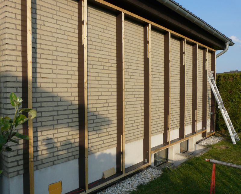
A frame of glued laminated timber is mounted to the wall. A routed notch at its back is used for compression tape to get an air tight, but diffusion open connection to the wall. The frame holds the PUR insulation. The orange foam at the left bottom temporarily closes one of the wall openings for the air; the other is at the right end. The connections between the fields are well visible.

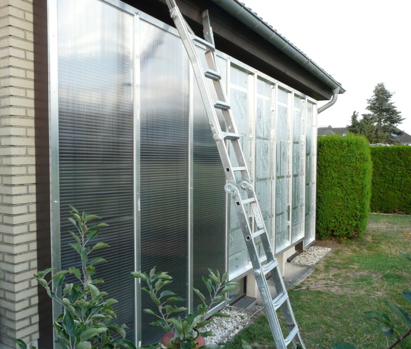
To benefit from the insulation even when there is no sun, I used 100 mm PUR and 140 mm timber, leaving a gap of 40 mm for the absorber. At the time of planning the construction, I was not aware of even minimal sun causing the collector to insulate the wall. Knowing that, now I would go with less insulation. The absorber consists of aluminum 25 mm blinds. Their plastic controls were removed, because they would melt, and a fixed angle suffices. All connections of material are taped with heat resistant aluminum tape for sauna construction. The glazing is held air tight by aluminum profiles. Here the first three fields were finished and the rest already has the insulation in them:

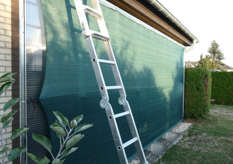
Some people just let the collector stand still during the summer. I am worried that the material may get stressed unnecessarily and cover it with a sun shading net. Some eye bolts allow to span a thin line over the collector field to provide some distance between the glazing and the cover. Lesson learned: The cover length appears to be measured stretched at maximum. I should have ordered it by unstretched length, but it still suffices to keep the temperature moderate.

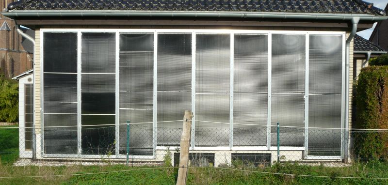
The first test revealed that the glazing bent inwards with increasing temperature: Due to its high heat resistance, it heats up and expands more inside than outside, thus bending inside by 25 mm, which restricted air flow and squeezed the absorber. I had to add two supports inside to restrict the bending to an acceptable amount. These are visible at the left side below. The other bright stripes are connections between absorbers, because I could not buy long ones due to supply restrictions at the time.

First I placed the outlet temperature sensor at the outlet, which is located at the bottom of the field. That did not work, because heat built up at the top of the collector and it took a very long time until the bottom heated up as well. Moving the outlet sensor away from the outlet toward the middle of the field fixed that.
The controller uses PT1000 sensors, which are sold encapsulated in stainless cases with heat resistant silicone cables. That works great for contact measurement, but air measurement is very slow. I bent some sheet metal and attached the sensor to that, which increased the contact surface to the air and resulted in much faster measurements.
The material expansion due to heat does put some load on all materials. I already knew from other collectors that I had to use 60 mm long screws to mount the glazing frames. I did not know that the PUR insulation also bends some under high temperature and needed to fixate it with aluminum profiles where needed. Most likely I need to do that in more fields.
The airflow pushed the absorber against the outlet. I bent some stiff wire to provide the needed distance, letting the air flow better.
I expected some problems and was prepared to take things apart and revise them as needed, and it went just like that, but in the end everything worked fine.
Results
Here are the results for October 9th 2022 to May 23rd 2023. The heating season ended mid May, which was quite late, and the overall sunshine was 25–30% less than during the last ten years. The collector will stay active, heating the house, until it is always pleasantly warm without.
The temperature was measured at the exit to the house and summed up as soon as it reached 30 °C. Expansion was not counted and the inlet assumed to be 20 °C, which was right in October, was not in November. So take the numbers with a grain of salt in both ways. In total, 1130 kWh were harvested at the price of 79 kWh electrical power.
How much gas did we save? That's hard to answer, because the temperature difference tracks the energy loss quite well, but the passive gains from solar energy cannot be measured easily. We also used the wood stove a few times. In absolute terms, we typically need 1700–1800 m3 per season and the finishing season needed just 1311 m3. I noticed the collecter often was above room temperature even when there was nothing to be harvested, which means it provided total insulation during that time. Future years will show if we just got lucky or if that's our new average consumption.
Conclusions
I kept track of all materials and ended up with a total cost of a little more than 3000 EUR. As I learned, I could have used less insulation and timber, which would have lowered the costs significantly. All material prices skyrocketed with inflation, but the developing politically caused energy crisis in Germany threatened me with extreme gas costs, so I went with buying significantly overpriced material, hence the insane price which in the end says something about the value of EUR.
The great insulation property at low brightness surprised me when I recognized it first, but it is easy to explain from the model and shows why the Trombe wall is actually a great design for warmer countries than Germany: Even when it does not suffice for heating, it often avoids the energy loss of the wall at very low cost.
Using timber is easy, but really a waste. A composite material of sheet metal and insulation foam would be cheap, light, durable, provide better insulation and lower the costs for mounting material. It would certainly be possible to come up with a modular kit solution for building large solar air collectors that is way cheaper than a DIY solution, likely more efficient and could be assembled at much lower labor efforts.
There were multiple decades time for the government to support some innovation, but it is a sad fact that no German political party takes environmental protection serious, which in particular includes the green party. Not even the energy crisis threatening citizens and economy sufficed to change minds. The extinction rebellion movement does not show any initiative for innovation either.
Solar energy is not an universal solution, but there is no excuse not to use its big potential where possible, especially if it is easy. However an affordable way to substitute some heating resources using solar energy would reduce tax payments and those together with the profit of energy providers are priority.