An integration sphere equalizes arbitrary light density distributions (spatial integration). There are two major applications for that: Measuring the total amount of light generated by a source with non-uniform density and generating a homogeneous field of light for illumination. The second is very useful for camera analysis.
Commercially built integrating spheres have great properties, but amazingly high prices. That's why many people build their own spheres. But how can their performance be measured?
The naive expectation is that the flux going into an integrating sphere is distributed over its inner surface, dampened by incomplete reflectance. That meant the flux at an exit port would be lower by the ratio of input port and sphere surface. But that expectation only holds for a plane surface. Taking the spherical surface into account, the output radiance is higher by the sphere multiplier, which results from the reflected light being reflected again, kind of like a light trap. This multiplier is larger than 1 instead of lower, as a reflectance would be:
$$\text"flux"_\text"output" = { \text"flux"_\text"input" · \text"surface"_\text"input" / \text"surface"_\text"sphere" } · \text"M"_\text"sphere"$$
This formula does not express that the light exiting the port is not parallel, which must be taken into account when measuring it.
The sphere multiplier depends on the fraction of the surface taken by open ports and the reflectance of the coating, because both lower the energy at each reflection. The total energy is the sum of all reflected rays:
$$\text"M"_\text"sphere" = ∑↙{i=1}↖{reflections} (\text"reflectance"_\text"surface" · (1 - \text"fraction"_\text"ports"))^i$$
This converges against:$$\text"M"_\text"sphere" = \text"reflectance"_\text"surface" / { 1 - \text"reflectance"_\text"surface" · (1 - \text"fraction"_\text"ports") } $$
It is recommended that the ports take at most 5% of the sphere surface. Commercial spheres have a multiplier of at least 10-30.
For details on the theory, I recommend
![]() Integrating Spheres - Introduction and Theory
and
Integrating Spheres - Introduction and Theory
and
![]() Integrating Sphere
Radiometry and Photometry. Both are very readable and explain the
fascinating way integrating spheres work.
Integrating Sphere
Radiometry and Photometry. Both are very readable and explain the
fascinating way integrating spheres work.
Solving the equations for $\text"M"_\text"sphere"$ and for $\text"reflectance"_\text"surface"$ can be used to determine the reflectance of the coating:
$$\text"M"_\text"sphere" = \text"flux"_\text"output" / \text"flux"_\text"input" · \text"surface"_\text"sphere" / \text"surface"_\text"input" $$ $$\text"reflectance"_\text"surface" = 1 / { 1 / \text"M"_\text"sphere" + 1 - \text"fraction"_\text"ports"}$$
Does the math work? I used a 6 inch commercial integrating sphere for verification.
The 2 ports (third one closed) have a diameter of 25.4 mm, resulting in a surface of 5.06 cm2 each. The diameter of the sphere is 152.4 mm, so the surface of the sphere is 729.3 cm2. This gives a port surface fraction of 1.4%.
Held into sunlight at a clear day to let the sun shine perpendicular into a port, the luxmeter showed a sun flux of 75000 lux and an output flux of 18700 lux.
$$\text"M"_\text"sphere" = { 18700 / 75000 } · { 729.3 / 5.06 } = 35.97$$
This calibration works, because a luxmeter contains a shallow cosine diffuser that lets it measure both collimated light (sunshine) and diffuse light (integrating sphere output near the surface).
The value would get lower if the third port was open.
$$\text"reflectance"_\text"surface" = 1 / { 1 / 35.97 + 1 - 0.014 } = 0.986$$
That matches the specification of about 98% surprisingly well.
The sphere consists of transparent plastic used for decoration to which I glued a flange for holding both halves together. The inside was painted with two coatings of silver to make it light tight and three coatings of white wall paint mixed with some titanium dioxide. The ports have metal rings attached with a T2 thread inside and a groove outside to hold accessories:
The 3 ports have a diameter of 41.5 mm, resulting in a surface of 13.52 cm2 each. The diameter of the sphere is 194 mm, so the surface of the sphere is 1181.8 cm2. This gives a port surface fraction of 3.4%.
The luxmeter showed a sun flux of 117000 lux and an output flux of 7200 lux.
$$\text"M"_\text"sphere" = { 7200 / 117000 } · { 1181.8 / 13.52 } = 5.38$$
Not 10-30, but the positive multiplier is clearly there. So what's the reflectance?
$$\text"reflectance"_\text"surface" = 1 / { 1 / 5.38 + 1 - 0.034 } = 0.868$$
That is in line with what can be expected from white wall paint. The extra titanium dioxide gave around 1.5% higher values to a previously tried coating without. That does not appear to be much, but it increased the sphere multiplier significantly, which means a more homogeneous field of light.
A more obvious way to express the sphere multiplier is by the number of reflections until it converges:

Even this simple integrating sphere reflects each ray many times, which results in the desired integration and the homogeneous distribution. A commercial sphere reflects the light much more often.
Note that the measured numbers are not accurate to the given precision. The luxmeter measure always varies some, depending on the sunlight and how perpendicular you hold the sphere.
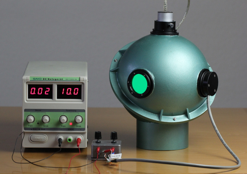
It is convenient to have an illumination with different wave lengths. I used LEDs with 462 nm (blue), 515 nm (green, close to night vision peak of 505 nm), 568 nm (green, close to day vision peak of 555 nm) and 632 nm (red). The illumination module is built from two milled pieces of POM and screwed directly into port. A baffle prevents light falling directly on another port. The brightness is controlled using a small constant current source with coarse and fine adjustment that delivers at most 20 mA, which forbids to accidentally destroy a common 5 mm LED.

According to the datasheet, the 568 nm LED delivers at most 2500 mcd at 15 degree transmission angle and 2.5 V with 30 mA, which gives upper limits of:
$$2 * π * ( 1 - \cos( 15 ° ) ) = 0.054 \sr$$ $$2500 \mcd * 0.054 \sr = 0.134 \lm$$ $$0.134 \lm * 5.38 / { 0.11818 \m^2 } = 6.1 \lx$$ $${ 0.134 \lm } / { 683 \text" lm/W" * 0.952 } = 0.19 \text" mW light"$$
5.38 is the sphere multiplier, 0.11818 m2 is the sphere surface and 0.952 is the efficiency factor for 570 nm.
Compared to the electrical power of 30 mA at 2.5 V = 75 mW that is rather poor and indeed this LED is much darker than all others I looked at, but perhaps that's the price to pay for the wave length.
Measured with a Lux meter at 2 V and 20 mA I get 4.2 lx, which about matches the theoretical 6.1 lx at 30 mA, because the light power is about proportional to the current.
Summary: A reproducible homogeneous field of light with known wave length and intensity can be created.
To measure the brightness of green or white light as perceived by a human,
a Lux meter works fine. Its spectral response is rather narrow and
usually not specified exactly, though, so measuring red or blue light
does not work well. Using a brightness sensor with a wide spectral
response works better. I use a TSL235 sensor, connected over USB using
![]() tps.
tps.
A green laser pointer creates the brightness of 3.09 μW/cm2. How much power does it have?
$$3.09 \text"μW/cm"^2 * { 1181.8 \cm^2 } / 5.38 = 678 \μW$$
That matches it being classified as < 1 mW.