3D printer setup: First part
Introduction
Before I started 3D printing in 2020, I thought that setting up a new printer was probably well understood after all the years. I could not have been more wrong. Much to my surprise, I found mostly unstructured trial and error advice, fairy tales and myths, but few analytical investigations. Time for some old-fashioned thorough work.
The preparation is probably the best understood procedure. I checked that:
- The rectangular angles are correct
- All axes move softly
- End stops and homing work
- The bed is levelled with Z position 0.00 mm meaning its surface
- The hot end and bed heat up the right temperature (correct NTC type) and PID control is tuned
- The hot end is mounted correctly without internal gaps
- The extruder is calibrated
- There is either no or at most a few 1/100 mm backlash in the axes.
- The filament is measured over some length at different angles and either meets the specification or at least has a consistent dimension.
The belt tension is missing from the above. Some Nema 17 motor datasheets specify a maximum radial force of 30 N at the center of the flat side of the shaft, which would be 15 N for the belt being wrapped around it and less if the pulley is further away. I will use 10 N here. The belts can often take more. The string vibration is:
$$\text"frequency" = √{ \text"tension" / \text"density" } / { 2 · \text"length" }$$
Example: 10 N tension, 0.0091 kg/m density, 410 mm length = 40.4 Hz. 15 N would be 49.5 Hz. The belt could take more, but the motor is a limit.
Preparation done, welcome to level 2.
The first part
The two main problem areas of a 3D FDM printer are kinematics and extrusion. Both show problems in printed parts, which makes it hard to separate them. The ideal start is printing a part that avoids many extrusion problems and allows to focus at kinematics first. These are the requirements:
- Extrude at low throughput, which lets filament spend a long time in the nozzle to melt well, resulting in low viscosity, low extruder pressure and little mechanical stress on the feeder.
- Extrude steadily with few direction changes that cause speed variations. A steady extrusion speed means constant viscosity and smooth prints.
- Have large enough areas where the kinematics work steadily, e.g. no curves, but straight lines
- Objects that consist of single line walls tolerate a wrong flow as long as there is enough to bond the layers reliably and not more than the extruder can provide reliably, avoiding defects from wrong flow.
- Enough layer time gives the part sufficient time to cool down to avoid curling or even meltdown.
- Both X and Y walls as well as diagonal walls: CoreXY mechanisms need both motors for X and Y movements, but only a single motor for diagonals. For other printers it is the opposite. The entire picture is interesting.
A temperature tower or heat tower shows which temperature bonds layers best while not overheating the filament. It does so by varying the temperature with the height. There are many temperature towers on the net, but most print rather long and need much filament, and in order to control each detail the slicer configuration needs to be adjusted heavily and preferably the gcode verified, too.
The complexity to generate suitable gcode for the admittedly uncommon requirements can be avoided by generating the temperature tower gcode directly using a small program, avoiding the slicer. The code does not use spiral mode, because that constantly moves the Z axis, which mixes errors in X/Y and Z. A few variables allow to customize it for a specific printer and afterwards you get 100% reproducible test prints:
As distributed, my temperature tower uses:
- Roughly 60x85 mm base size: Reasonable layer time and good inspection areas
- 5 mm brim to check the levelling and increase bed adhesion
- 0.1 mm layer height: A multiple of a full step in Z for my printer and fine enough to provide smooth walls.
- 0.4 mm line width for good bonding: The diameter of the nozzle in my printer. Exceeding it moderately is possible, but I don't want to hit the limit here.
- 95% flow: This allows for some voids in the brim and is otherwise not relevant for this part. Reduce if you get problems with the brim.
- −1 K/mm temperature change per height: Distance in mm gives temperature
- 40 mm height: 40 K temperature span
- 30 mm/s print speed: low extrusion throughput
- Start temperature depends on the filament and hotend
The extrusion throughput is:
$$0.95 · 0.1 \text"mm" · 0.4 \text"mm" · 30 \text"mm/s" = 1.14 \text"mm"^3 / \text"s"$$
That does not challenge a common hotend like e3d v6 in any way. The layer time is:
$${ 3 · 50 \text"mm" + 2 · 35 \text"mm" } / { 30 \text"mm/s" } = 7.3 \text"s"$$For long single line walls, that time is sufficient to let the part cool down enough before the next layer even without part fan. If the part fan is mounted correctly, a tower with and without fan should not show a difference. A smaller tower would have to be printed at lower speed, which saves some filament, but does not save time, and you had a smaller inspection area.
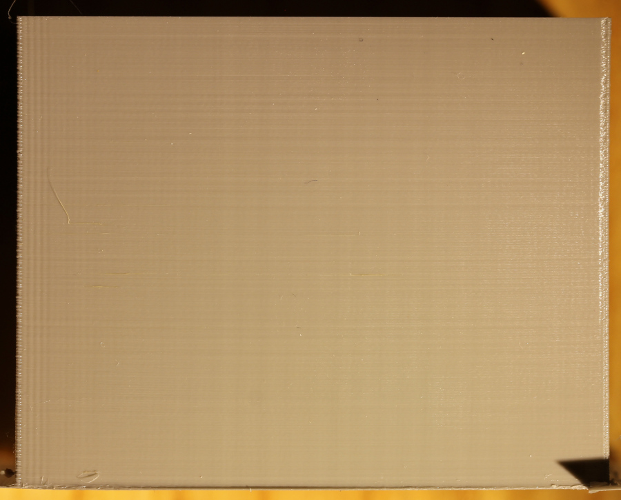
The result depends on the filament. Some filaments show a temperature specific difference in the surface and breaking the layers with the fingernail gives a clear indication of the best temperature. Others look the same everywhere and the effort in breaking them only differs slightly. That was the case for my filament, so I decided for the middle between points where layers break more easily at 225 °C.
The visual inspection shows nothing special really. There are slight ringing at the left edge and some minor stripes.
The idea was to create a part that mostly depends on temperature and kinematics. Now that the temperature is right for this speed, the kinematics can be checked.