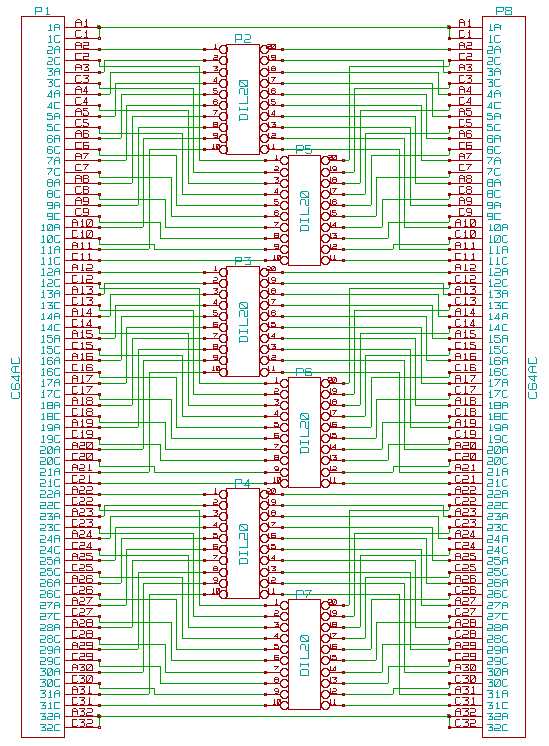
A bus extender is very useful as soon as the backplane contains more than one board, because the board to debug can be accessed easily from both sides to measure signals. Small switches can disconnect all bus lines and serve as access points to watch the bus signals, too. The unused board space is filled with copper connected to ground. The actual signals only run on the copper side, so you could easily omit the ground plane on the component side and build this on a single sided board. The schematics are trivial, but it is a nice pattern:
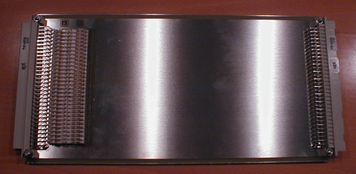
I decided not to buy a few meters wire, but send a layout to a PCB fab for the first time ever. As you can guess, I made some mistakes. The board was a little too wide, but better too wide than too narrow. Worse, I put the switches too near to each other. Sanding them about 0.5 mm each allowed to solder them in. Other than that, everything was fine.
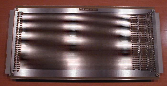
The mistakes made in the prototype are corrected. You can download schematics and layout for Kicad as ZIP archive.
The board has 4 vias. If you solder the connector pins 32a and 32c from both sides, you can use a cheaper PCB fab without vias.