In the beginning of ECB, the integration density enforced very modular
systems with CPU, memory and even most essential I/O hardware each on
their own card. The eighties already allowed to build single board
computers with everything onboard and an ECB interface for extension
cards. I decided to put what I consider the essential core of any system
on one card: CPU, ROM, RAM, a battery buffered RTC, a serial console port
and of course the ECB interface. The RAM is battery buffered, because
that way I don't need NVRAM and the RTC needs battery backup anyway.
If the CPU would not already contain a timer, I would have added one
as well. Being used to rackmount systems, I added a message LED and a
board temperature sensor. I cared about power consumption and although
the hardware fills a whole eurocard (160x100mm), it only needs around
30mA at 5V. See the ![]() hardware description
for details.
hardware description
for details.
Back then, most systems offered either a simple boot monitor with one-letter commands, or BASIC, both written in assembler, with a few builtin device drivers allowing to boot from mass storage, and not made to be extended by more device drivers. Worse, changing the CPU architecture required rewriting everything. Sun showed how to solve this problem, so I went a similar route and implemented a simple Forth system as boot monitor.
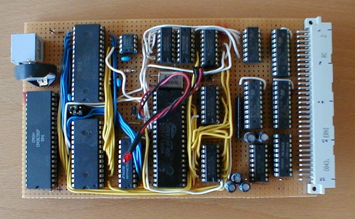
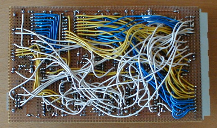
I admire people who build prototypes that don't look like a mess, but at least I am not the only one who does not master that art. At the left is a RJ45 connector for the serial console, using Cisco style pinout, at the right is the ECB connector. In between there is lots of wire and less than optimal placement as a result of various major changes, but: It works.
You can download schematics and layout for KiCad as
![]() ZIP archive (generated Gerber files, drill
file and CWK file for fab order included). Further, there is the source
for
ZIP archive (generated Gerber files, drill
file and CWK file for fab order included). Further, there is the source
for ![]() a couple diagnostic programs and the Forth monitor.
a couple diagnostic programs and the Forth monitor.
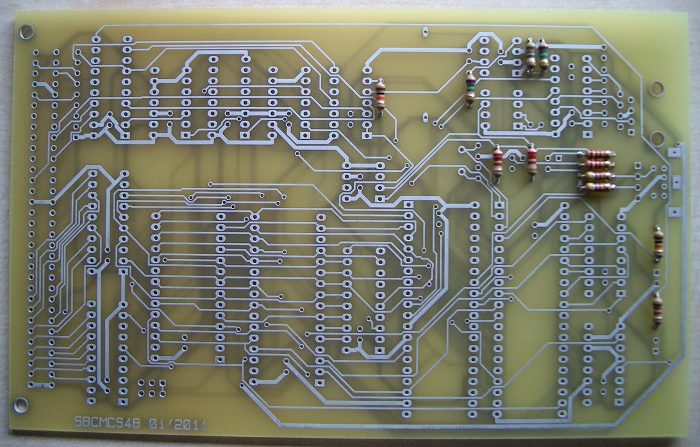
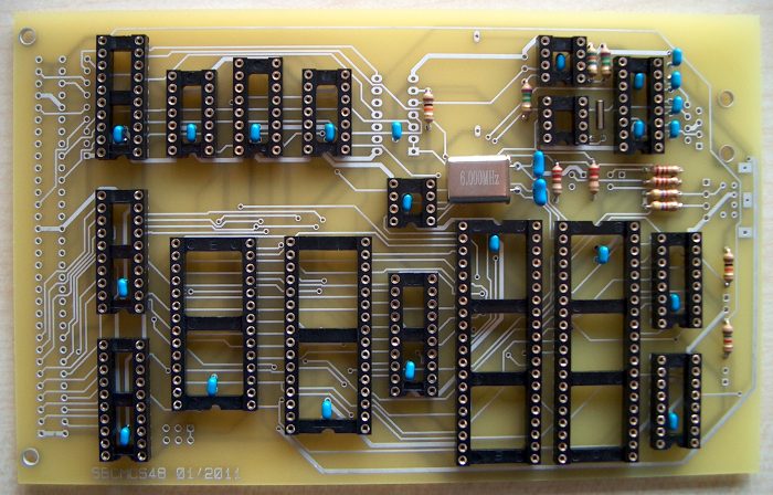
I ordered a prototype PCB at ![]() PCB Pool
and was very satisfied with their service, but of course found some problems
of my own. Let's start with a picture with resistors mounted:
PCB Pool
and was very satisfied with their service, but of course found some problems
of my own. Let's start with a picture with resistors mounted:
So far, so good. Then I mounted the next flat parts and found out my partlist contained only two 14 pin sockets, but I need three:
Next surprise: The Mini-DIN-6 footprint I got from the net was wrong. As you can see at the right side, the holes are way too small. Next I found out I got the wrong kind of RJ45 connector. Mine was smaller than the footprint. As it turned out, the footprint was right, because all network cards I checked had a connector like it. Desoldering one from a broken card solved the issue. Since I wanted unshielded parts, but got shielded ones, I put some tape below them to prevent short circuits.
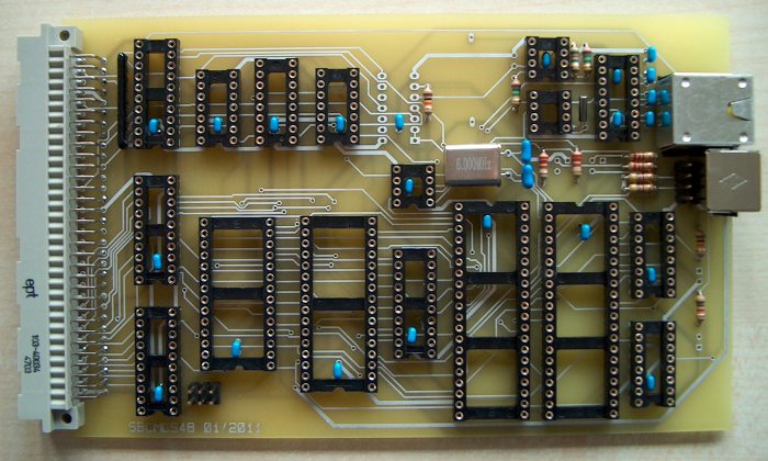
Yet another surprise: The footprint for the battery socket was too small and the pads had slightly too small holes. The real part covers two resistors, so I desoldered them and moved them to the copper side.
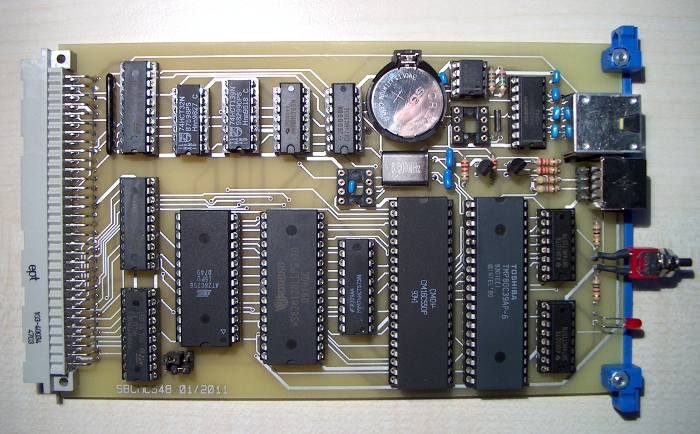
I checked the board did not contain a power shortcut, populated the chips and turned it on. Now I could tell how great it worked and everybody would think how cool I am - but I would lie. Since the CPU did not even enable the multiplexer, I could tell fetching instructions failed. Rather quickly, I found a shortcut between A14 and Vcc. I did not see it, but could measure it, and resoldering the ROM jumpers fixed it. Still no response from the board, but at least it enabled the multiplexer now. Using a logic probe, I saw the UART got accessed, but could not tell more. I built a single step circuit and attached it, which showed the program accessed the UART exactly when it should, but something was wrong, because it did not react. I saw /WR and /CS active, but together? Logic probes can't tell (my next one will have a trigger), so I built a latch with some LEDs, attached that to the board as well, and soon I saw the UART /CS was not active when /WR was. The decoder worked fine, but the address bus did not. This time, it was a minor but important drawing mistake in the schematics, so I fixed the schematics by exchanging the connection to P2.6 and P2.7, then fixed the PCB, and finally the SBC booted up. The front shield and the I2C chips are still missing above.
The released files above contain those fixes. I also changed the placement after the prototype, so the PCB looks different than the prototyep above (version SBCMCS48 02/2011).
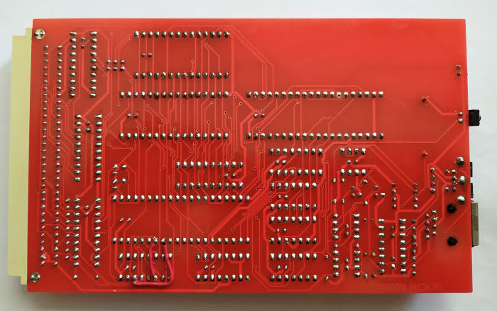
9 years later I got a bug report that the connections to P1.6 and P1.7 are also wrong and need to be exchanged. Kicad refuses to load my old schematics, so I cannot fix that. Thanks a lot to Jan Meloun for the bug report and the images of the version 02/2011 PCB.
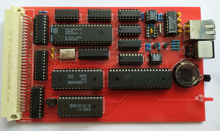
The back shows the needed revision for the multiplexer lines.